The volunteers who have a goal of providing Meshcore coverage in the mountains of Colorado do not have it easy. The antenna provided on an “off-the-shelf” LoRa repeater usually turns out to be inadequate for the needs of a high-elevation site where the next repeater is perhaps forty miles (sixty kilometers) away. We build our own repeaters, using parts from many sources, and we find it necessary to do acceptance testing on the parts. This article talks about acceptance testing of the LoRa antennas that we use in our mountain repeaters.
As just mentioned, to provide Meshcore service in the mountains of Colorado, we find that we must build our own LoRa repeaters rather than using commercially available or “off the shelf” devices. There are several reasons for this.
A first challenge is that a repeater at, for example, a site on a mining claim near the top of a mountain will needs to stand up to gale-force winds and other harsh environmental conditions (and an “off-the-shelf” repeater is unlikely to survive such conditions).
A second challenge is that at high-elevation mountain locations, temperatures can drop to tens of degrees below freezing. This puts into question whether an ordinary lithium-ion battery or cell can receive charging current, or can supply operating power to the LoRa radio, over the expected range of operating temperatures. We explore alternative cell chemistries such as lithium-iron-phosphate and lithium-titanate-oxide. We over-engineer a conventional lithium-polymer cell, hoping that if we make it twenty times bigger than it (theoretically) needs to be, it might provide adequate service even at low temperatures.
A third challenge is that during winter, the sun is low in the sky and days are short, and it is sometimes cloudy, which limits the amount of charging energy that can be collected by a solar panel in the course of the day. This prompts us to use a much bigger solar panel than one might think to use under less demanding conditions. And we explore use of (for example) an MPPT charging controller rather than a simple controller such as we find in an off-the-shelf LoRa baseboard, so as to extract as much energy as possible from the limited available solar flux.
A fourth challenge is that if a repeater were to stop working because of a low battery, when the battery slowly warms up and gets recharged (from a solar panel), one cannot be sure that the microcontroller will boot up properly and return to normal service. So we explore changes to the existing repeater firmware, and we explore use of an external watchdog device.
A fifth challenge, as mentioned at the start of this article, is that in the mountains of Colorado, it often turns out that a location of a planned new repeater will be tens of miles away from any existing repeater. The ordinary antenna that might be just fine for a Meshcore repeater at a residential site in the Front Range will almost certainly turn out to be woefully inadequate for a mountain location. So we explore higher-gain antennas such as the yagi and fiberglass antennas that are the subject of this article.
A sixth challenge is that a typical mountain location for a repeater is hard to get to. Many Colorado mountain Meshcore repeater locations may be reached only after an hours-long hike or a difficult four-wheel-drive excursion. Some Colorado mountain Meshcore repeater locations are literally inaccessable during the winter. This means that we must try very hard to construct a repeater that is likely to keep doing its job even after many months without any in-person visit.
A seventh challenge, as anyone knows who has deployed a Meshcore repeater, and who paid for it out of his or her own pocket, is cost. We cannot afford to use the expenditure of lots of money as a way to get parts of acceptable quality; we must shop around. When we shop around for parts for our mountain repeaters, we end up needing to test the parts. We cannot simply assume that some part from a particular vendor will do the job. We must do acceptance testing.
Many of your Meshcore volunteers in the mountains of Colorado draw upon ham radio experience.
Having set this background, I now turn to acceptance testing of high-gain LoRa antennas. In the mountains of Colorado we find ourselves using fiberglass vertical antennas (typically claiming a gain of 5.5 dBi) and directional yagi antennas (typically claiming a gain of 8 dBi).
One figure of merit for an antenna is its SWR (standing wave ratio, Wikipedia article). A radio operator will typically set a goal of having an SWR of 2 or smaller. Most antenna makers will promise that their antennas provide an SWR of 2 or smaller across the target range of frequencies. We were disappointed with the SWR in two recent batches of antennas, as I will describe.
In the old days, a typical way to evaluate an antenna was by means of an SWR meter, measuring the SWR at a time when a radio is transmitting. Such a measurement reveals the SWR at whatever frequency is being transmitted at that moment. This does not tell us what the SWR might have been at some other frequency within the target range. In the old days, an evaluation of SWR across an entire target range of frequencies would require a VNA (vector network analyzer) which might cost as much as a house and might be so big and heavy that it takes two hands to pick it up.
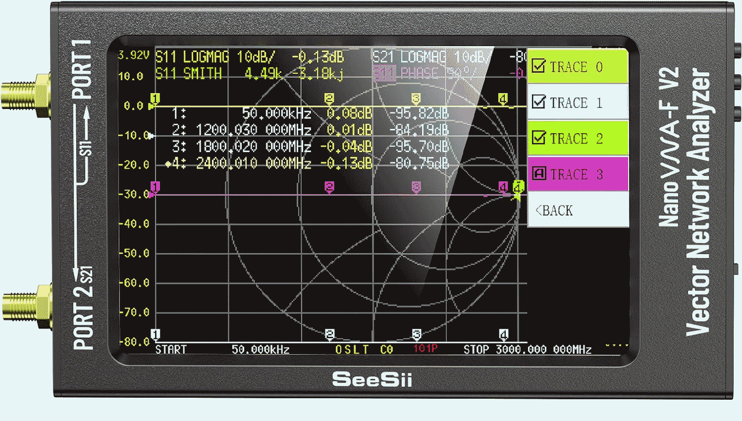
In recent years a remarkable device called a nanoVNA has become available. The nanoVNA is the size of a pocket calculator. The model I used in today’s testing is a nanoVNA-F V2. The “F” means that it has a sturdy aluminum case and a 4.3-inch display and a 5Ah lithium-polymer cell. The “V2” means that it can work at frequencies as high as 3 GHz. The dimensions are 5.51 x 2.95 x 0.79 inches or about 14 x 7.5 x 2 cm. (This nanoVNA cost about $125.) The device can be used with notebook computer software called nanoVNAsaver to capture results such as are shown in this article.
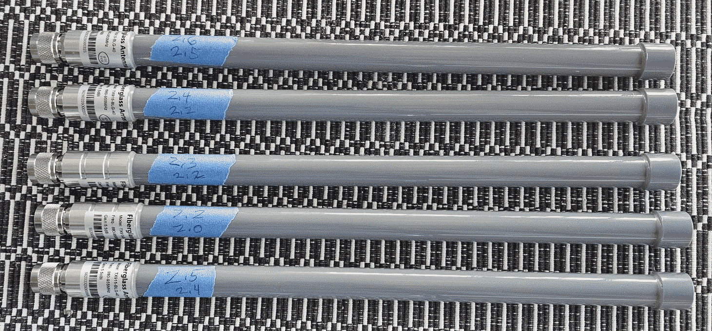
We will start with a batch of seven fiberglass antennas, some of which are shown at right. Each antenna is about 35 cm (14 inches) tall and has a male N connector at its base. These have model number TX915-BLG-40, with a claimed gain of 5.5 dBi and a claimed SWR of 2 or better over a frequency range of 880 to 955 MHz. They cost about $16 each.
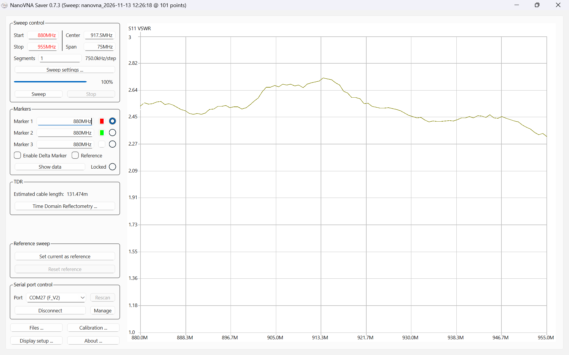
One of the antennas in this batch has a serial number of S6200326000442. As you can see in the test results at right, over the target frequency range range, the SWR for this antenna was never even as good as 2.3, and got to be as bad as 2.7. I returned these antennas to the vendor and made a note not to use this vendor in future.
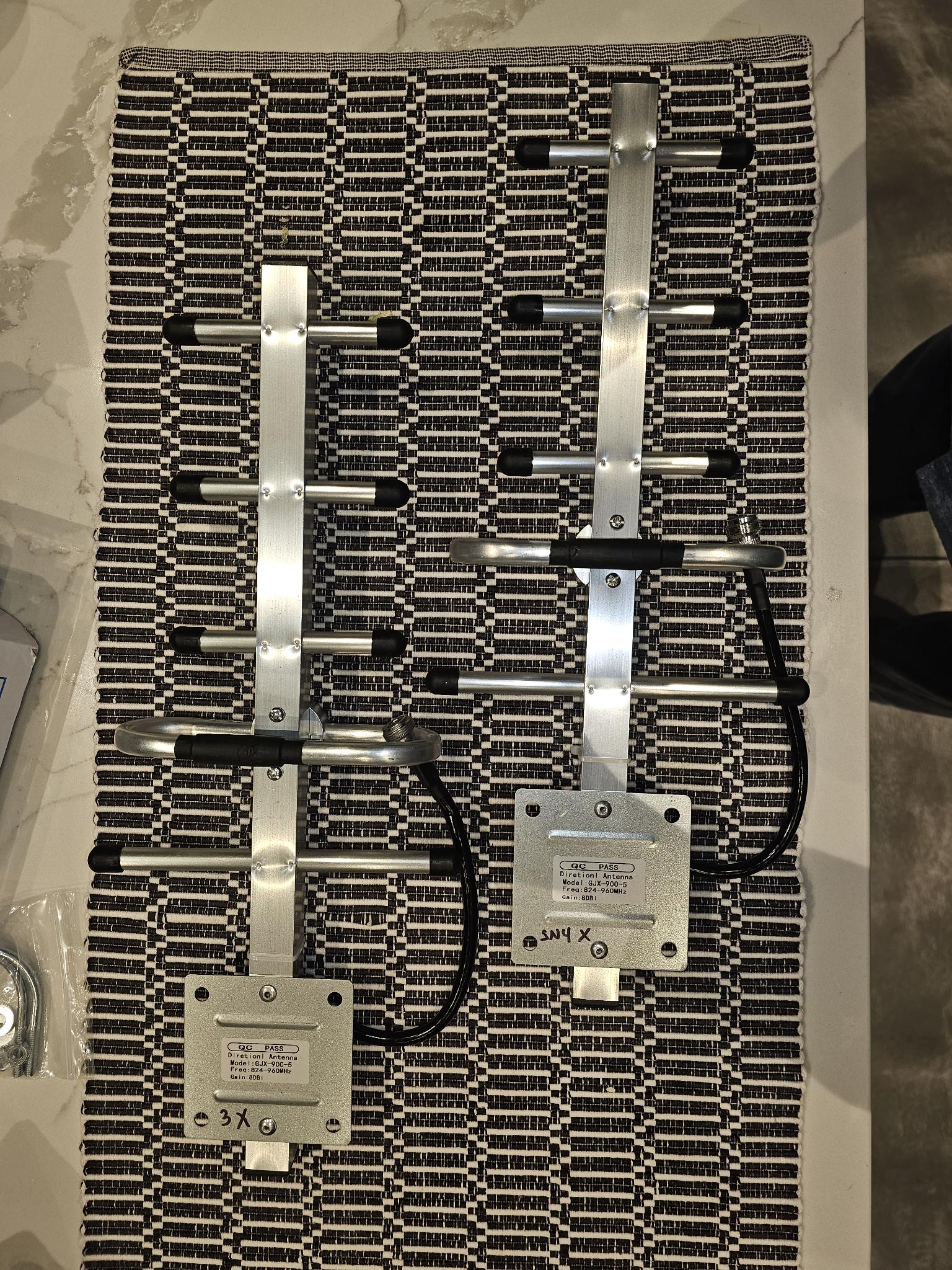
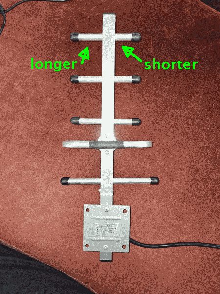
Now we turn to a batch of four yagi antennas, two of which are shown at right. The vendor did not put the antennas into a box, but instead merely shipped them in a bag. This exposed the antennas to a risk of damage during shipment. As may be seen, these are five-element yagis and have a model number GJX-900-5, with a claimed gain of 8 dBi and a claimed SWR of 2 or better over a range from 824 to 960 MHz. The connector is a female N connector. The antennas cost about $15 each.
Two of the four antennas tested just fine, but the other two antennas turned out to be defective.
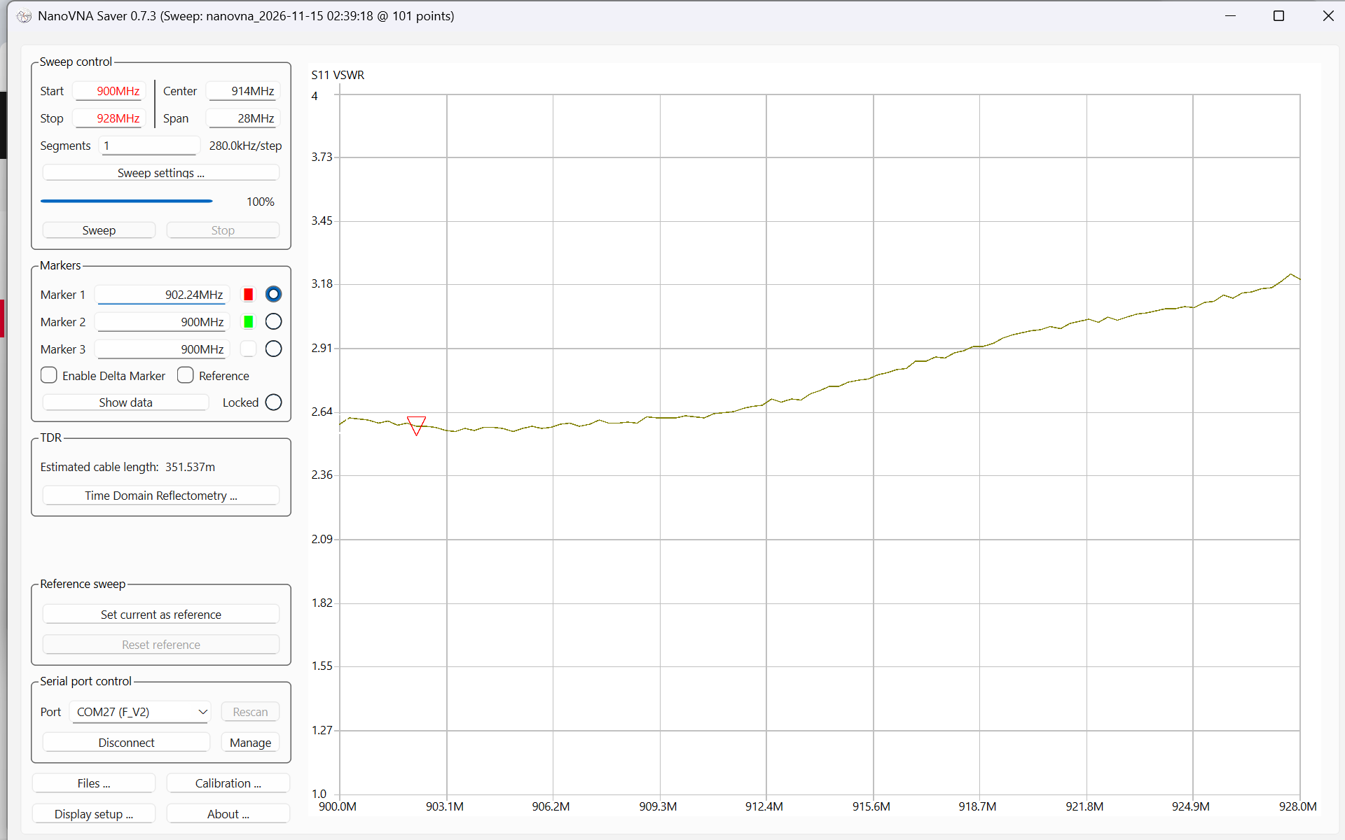
At right we see the SWR test results for one of the antennas. We did not worry about SWR over the full claimed range of 824 to 960 MHz, but instead we looked closely at the SWR over our particular range of interest which was 900 to 928 MHz. As you can see, over our relatively narrow target range, the SWR for this antenna was never even as good as 2.6 and got as bad as 3.1.
Visual inspection suggested that at least one factor helping to explain the unacceptable SWR values was damage during shipment. The reflector element on this antenna had gotten pushed aside, and was no longer centered in its mounting arm.
But visual inspection also suggested manufacturing defect as a factor. In a proper yagi antenna, the director elements get shorter as one progresses in the forward direction. But the forward-most director element in this antenna was longer than its adjacent neighbor.
I am returning the two defective antennas to the vendor.

Leave a Reply