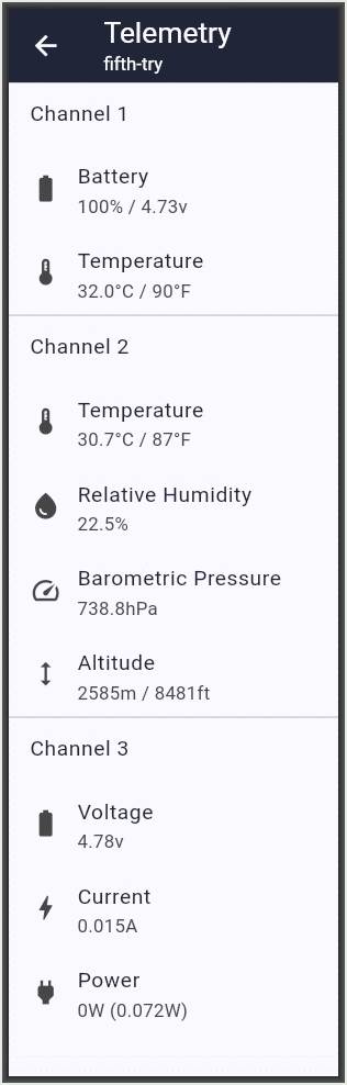
Newly constructed repeater 1W14, powered by purple Hakadi-branded LTO cells, operating at 1W and using a full-wave antenna, is now in test. It is able to monitor battery current using an INA219 current sensor.
(Also in test are newly constructed repeaters 1W9 and 1W10, which you can read about here and here.)
The 1W10 repeater uses a RAK WisMesh 1W Booster Starter Kit which is SKU 116256. This is the “battery powered” variant for the US915 MHz market. The solar panel is said to be 5 volts and 5 watts. The antenna is a fiberglass 915-MHz antenna with a male N-type connector.
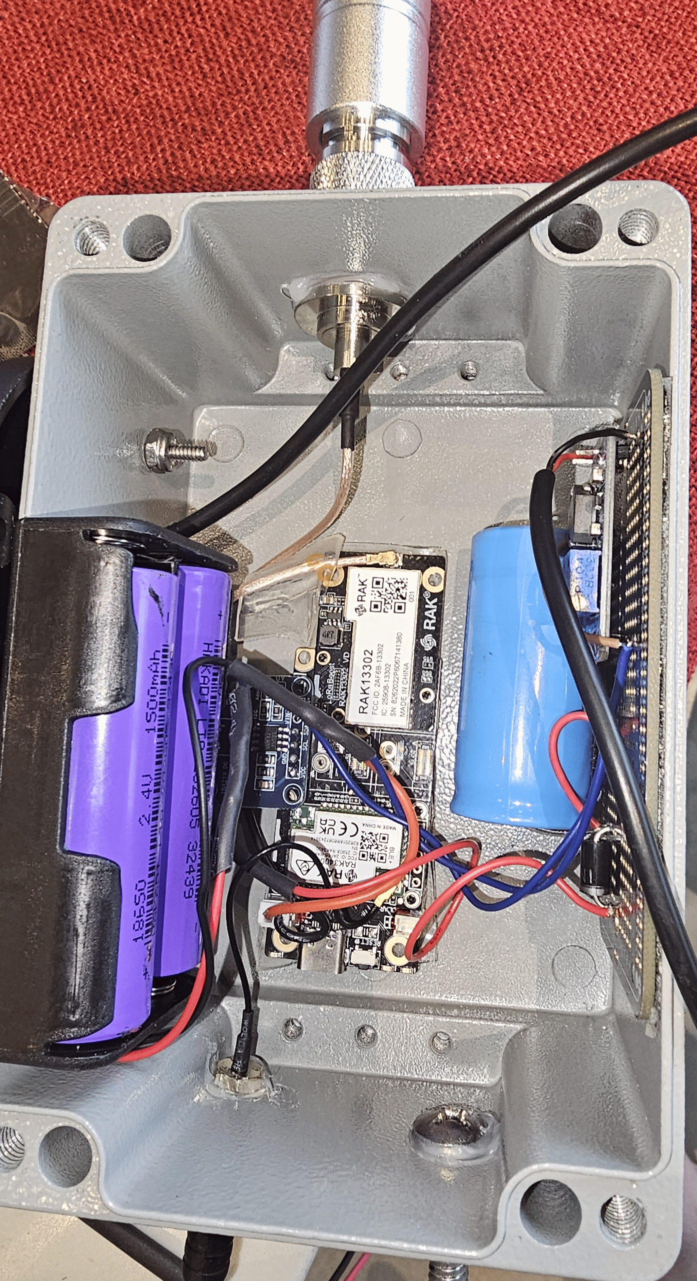
The interior of the repeater box may be seen at right. The solar panel is connected to the input of an MT3608 buck converter which hopefully has been set (using the potentiometer) to an output of 5.6 volts. The converter’s output passes through the 1N5404 diode that was just mentioned. You can see a 5600-μF 40V electrolytic capacitor across the output. The battery is composed of two LTO (lithium-titanate-oxide) cells.
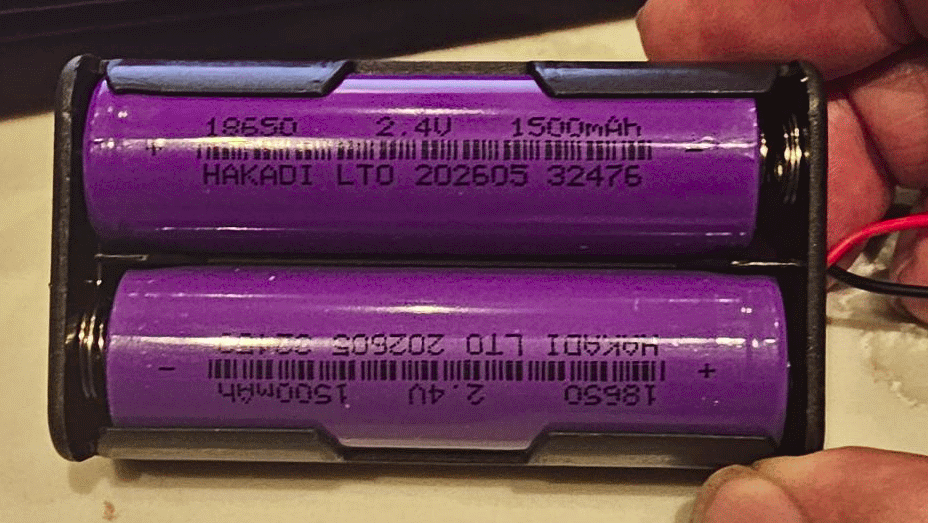
Each cell (seen at right) is an LTO 18650 flat-top cell with nominal voltage 2.4V and rated capacity 1500 mAh. Each cell cost around $3 from Hakadi (shopping cart page).
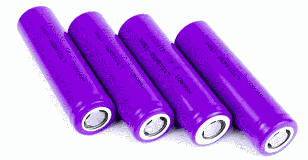
There is built-in circuitry in each cell to bleed off as waste heat any charging voltage above 2.8V, and the circuitry cuts the battery out of the circuit if the battery voltage drops below 1.5V. Two cells were placed in series to form a battery with nominal voltage 4.8V.
The charging voltage might be 5.6V which is too high for the radio. (The power input of the radio is intended to be in a range of 1.8V to 5.5V.) So a second 1N5404 diode is used to cut the power supply by about 0.6V, to slightly under 5V.
It is important to recall that the battery connector on the radio is wired “backwards”, so a standard PH2 battery cable needs to be wired using black as positive and red as negative.
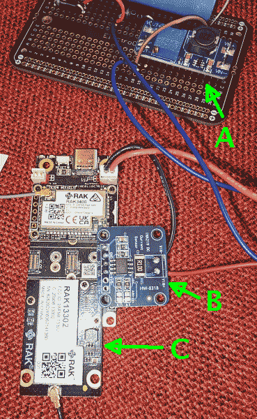
You can see part of the assembly of the repeater at right. You can see the one-watt radio C, the INA219 sensor B, and MT3608 buck converter A.
This repeater 1W14 uses a Bosch BME280 sensor for humidity and barometric pressure, and also uses an INA219 sensor for current to and from the battery.
Just as in newly constructed repeater 1W9, a Bosch BME280 sensor was added to the radio as described here. This uses the I2C bus of the RAK 19007 baseboard. It measures temperature, humidity and barometric pressure, made available to software at telemetry channel 2.
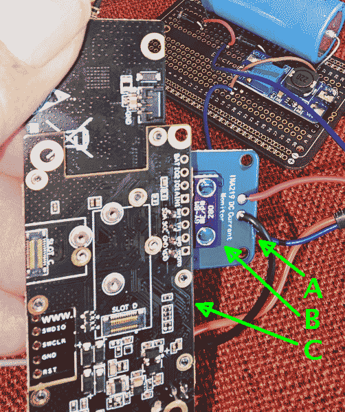
It was no easy trick figuring out how to connect up the radio itself with the humidity sensor as well as the current sensor. At right is one view of the result, showing the current sensor A, the humidity sensor B, and the radio C, the latter being stacked up on header pins, not easily seen in the photo.
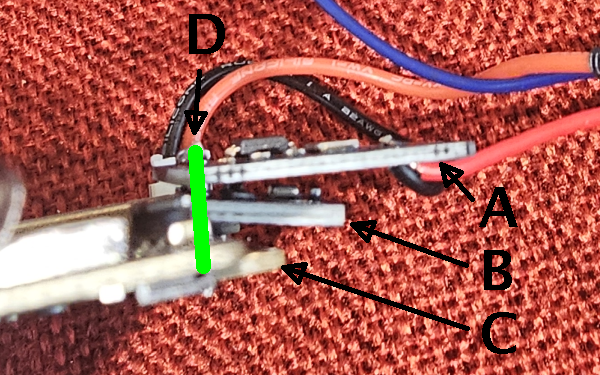
An edge view at right shows the stack. At the bottom of the stack is radio C. Four header pins stick up from the radio C, positioned as indicated by the green bar. These four pins provide the four lines of the I2C bus and provide the physical support for the BME280 sensor board B and the INA219 sensor board A.
The reader will perhaps share my astonishment at the cleverness of the volunteers who crafted the Meshcore repeater firmware. At boot time, the firmware scans the I2C bus and learns of the existence of the BME280 sensor board B (defining it as telemetry channel 2, seen in the report at the top of the page) and the INA219 sensor board A (defining it as telemetry channel 3, again seen at top).
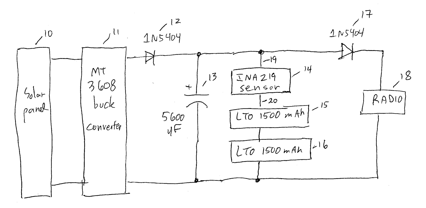
At right you can see a simplified schematic for the repeater. Solar panel 10 provides a nominal 5V and 5W to the MT3608 buck converter 11. The real situation is that the output of the solar panel 10 might be 5V or 4V or 3V. The goal of the MT3608 is to provide a fairly constant output voltage to diode 12 and capacitor 13 across any of a wide range of output voltages from the solar panel 10. The output voltage from the MT3608 is very much a function of the behavior of the most recent person who touched the potentiometer at the buck converter 11. My best recollection is that I initially adjusted the pot so that the open-circuit voltage at capacitor 13 (which is down by one diode voltage drop because of diode 12) was about 5.6V. (I say “initially” because as mentioned below, I later dialed down the pot a bit to avoid delivering too high a voltage to the radio 18.) I say “open-circuit” to describe how it was before I connected the battery 15-16 to the capacitor 13. With the battery 15-16 connected, the voltage at the capacitor 13 would typically drop to around 4.8V, I think because the two cells 15, 16 each have LTO battery chemistry that tops out at around 2.4V.
The situation is murkier when one recalls that each cell 15, 16 has protective circuitry inside, that limits voltage across each cell to around 2.8 volts. This hopefully provides balancing for the two cells 15, 16. And the situation is murkier still considering that diodes 12 and 17 are Schottky diodes, having a voltage drop that is smaller than the usual silicon diodes that I wish I had used in this circuit.
The next problem is that the radio 18 is only able to accept at most around 5.5V at its battery input. So a second diode 17 is provided to drop the voltage a bit more. My best recollection is that I adjusted the pot at 11 down a bit more so that the measured voltage at radio 18 was around 5V.
We now need to talk through the two voltage readings appearing in the telemetry report at the top of this article. Every Meshcore repeater has a telemetry channel 1, but this particular repeater 1W14 also has a telemetry channel 3 which is the INA219 sensor 14, and it also reports a voltage. The telemetry channel 1 comes from the radio 18 itself. We thus appreciate that the two voltage measurements are separated by a diode drop from diode 17.
The INA219 sensor board (spec sheet) is a six-terminal device. It has two terminals 19, 20 for current measurement. And it has four terminals for its I2C bus, omitted for clarity in the block diagram. The current measurement takes place at a 0.1Ω resistor across terminals 19, 20. But conspicuous by its absence in the block diagram above is the answer to the question “how does the voltage get measured?” The answer turns out to be “the voltage is measured between terminal 20 and the ground of the I2C bus”. The ground of the I2C bus is the same as the power ground for the radio 18.
The repeater is housed in an aluminum weatherproof box (shopping cart page) that is 5.9 by 3.9 by 3.1 inches (150x100x80mm). Here is a list of the external penetrations:
- N-type bulkhead female connector on top (for LoRa antenna)
- SMA bulkhead male connector on bottom (for Bluetooth antenna)
- ¼-inch machine screw on bottom (for bracket mounting)
- two 3/16-inch holes on side (for mounting the solar panel)
- one ¼-inch hole on side (for entry of power cable from solar panel)
An effort was made to seal all penetrations with silicone caulk.
The radio was flashed with the 0.9.2-OTAFIX2.2-BP1.3 bootloader and v1.17.1-d929643 (Build: 14-Aug-2026) Meshcore repeater firmware. Its test name is 1W14.
The antenna (shopping cart page) is said to have 5.8 dBi gain.
Here are some neighbors:
- Windy Point – 12 dB
- Riley – 11.75 dB
- Ruby Ranch – 11.75 dB
- Ptarmigan – 11 dB
- Cottonwood – 10.75 dB
- Baldy Yagi – 10.75 dB
- Lake Hill – 9.75 dB
- Hamilton Creek – 9.5 dB
- Tenderfoot – 8.25 dB
- Mount Royal – 6dB
- Victoria – -2 dB
- Swan Mountain – -2.5 dB
- Williams Peak – -7.5 dB
Given that the radio draws a quiescent 30 mW, one might expect the battery to last several days without sunlight. The LTO chemistry is said to work down to -40°.